1. Introduction
The FEM (Finite Element Method) is a way of obtaining a of finding a solution to a physical problem. It relies on discretizing a continuum domain into finite elements. The accuracy of the solution greatly depends on the number of elements used to represent the physical domain. As we progressively refine the mesh, the solution improves and given enough iterations it converges towards a specific result. If there is an analytical solution for the given problem, the mesh refinement procedure will converge towards the exact solution.
However, there are situations where the solution does not converge with mesh refinement. Stress singularities are one of these situations. This article puts its focus on stress singularities and stress concentrations. What are they? When do they pose for concern? How should we, as FE analysts, deal with them?
2. Stress singularities
In structural analysis, we are mainly concerned about displacements and their derivatives – the stresses. A stress singularity is a point of the mesh where the stress does not convergence towards a specific value. As we keep refinement the mesh, the stress at this point keeps increasing, and increasing, and increasing… Theoretically, the stress at the singularity is infinite.
Typical situations where stress singularities occur are the appliance of a point load, sharp re-entrant corners, corners of bodies in contact and point restraints. As you can see, stress singularities are a common situation in FEA. The analyst must use his knowledge to determine the possible singularity locations and see if they are of importance for the model or not.
Although stress at these singularities is infinite, this does not mean that the model results are incorrect overall. First of all, the displacements are correct even at the singularity point. On the contrary, the stress at the singularity will pollute the stress results near the singularity, however some distance away from the singularity the stress results will be fine! This is an immediate consequence of St. Venant’s Principle. Perhaps one of the most important principle in FEA as it validates FEA results even with the presence of singularities.
St. Venant’s Principle
St. Venant’s principle states that the effect of local disturbances to a uniform stress fields remains local. Further away from the disturbance the results will not be perturbed. How far away? Typically, as far away as the size of the disturbance.
St. Venant’s principle allow engineers to dismiss stress singularities when the stress near the singularity is not of interest. For example:
- Application of loads.

Uniform tension load applied to specimen . The stress distribution at the vicinity of the applied load is not uniform. However, the stress becomes uniform some distance away of the applied load [1].
Even if the load is applied as a singular point load creating a stress singularity (σ = P/A and A=0 → σ=∞), the stress distribution away from the applied load will be correct as shown in the image above. Therefore, if we are not interested in the stresses near the singularity point, we should only be concerned about transmitting the resultant load P to the specimen. It does not matter if this is done through a point load or a pressure load, as far as the resultant is transmitted the stresses at the central section will be correct.
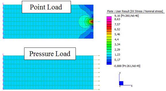
2D uniaxial bar model. A single point load leads to stress singularities whereas an edge pressure results in a uniform stress field.
As you can see, far away from the point load singularity the stress field is uniform despite of the local singularity. Note that pressure load do not cause point singularities, this is because the pressure attribute is converted by the solver into a set of point loads along the nodes of the edge in a consistent fashion that do not cause a singularity.
- Sharp re-entrant corners.
Sharp re-entrant corners are corners of a mesh which external angle are less than 180º a stress singularity occurs. In the mesh shown below this angle is 90º, an angle of 0º would represent the tip of a crack. In both cases this corner leads to a singularity. No matter how much we refine the mesh, the stresses will not converge at the vicinity of the corner. Nevertheless, St. Venant’s principle states that this singularity only pollutes stress results nearby, allowing us to use stress results away from the corner. The local singularity and its effect is shown in the following image.
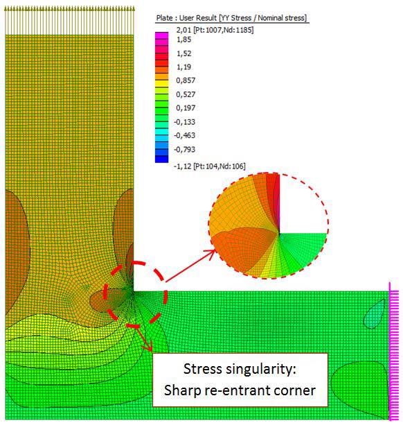
Typical sharp re-entrant corner of 90º – Contour of the stress singularity and its local effect.
The image above is a contour of the global vertical stress over the nominal applied stress at the top. The L structure has been modelled as a plane stress model, typical aluminium properties have been assigned and the right most edge nodes have been restrained. It can be seen that the most compressive and tension stresses both happen to occur at the corner. Therefore, the maximum and minimum stresses of the legend will always increase with mesh refinement!
In reality, no corner can be perfectly sharp. Even if desired, a manufactured sharp corner will always present a small fillet radius. This means that the stress will not be infinite anymore, the corner singularity will disappear. Instead, a stress concentration takes over.
3. Stress concentrations
When a large stress gradient occurs in a small, localized area of a structure, the high stress is referred to as a stress concentration [2]
A stress concentration is a place of the mesh where the stress raises above the applied nominal stress. It behaves in a similar fashion than stress singularities, but the stress will converge towards a finite value, not infinite, given that the mesh is sufficiently refined. Stress concentrations occur when the load path is deviated by the presence of harder or softer features or a change of geometry. For example, such features can be the presence of a hole in a plate mesh, fillet corners, a change of cross-section, etc. Contact forces are another common stress concentrations. High stress gradients also occur near the point of contact and rapidly subside as we move away from the contact area.
Let’s consider an infinite plate with a small circular hole. The applied stress is called the nominal stress. Typically the nominal stress is the stress field that would result in the structure without the stress concentration feature – in this case without the hole. As a consequence of the hole, the stress nearby will raise. The radial stress must be zero, there cannot exist stress radially as there is no material in this direction. The increase in stress will be noted in the theta direction, along the perimeter of the hole where the stress keeps increasing with theta, a maximum is found analytically when theta is 90º or 270º. The maximum stress is equal to 3 times the nominal stress. Therefore, for an infinite plate under uniaxial tension with a small hole the ratio between the maximum found stress and the nominal stress is 3. This ratio is the so-called stress concentration factor.
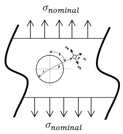
Stress concentration for an infinite plate with a small hole under uniaxial tension. (Kt=3).
Stress concentration factor: Kt = σ max / σ nom
The nominal stress is calculated using basic elasticity formulas based on the cross-section of the structure. Sometimes the net section (the section accounting the stress concentration feature) is used, otherwise the gross section is used. Once we know the nominal stress, the stress concentration factor can be found in tabulated data in the literature. E.g. [2] and [3]. And the maximum stress can be then retrieved.
A FEA model can be prepared to check this results. A 2D plane stress model of the plate with a hole has been modelled and it is subjected to an arbitrary pressure load at the top edge. Note that only quarter of the model has been modelled, taking advantage of the symmetry conditions. First, a coarse mesh is prepared for the purpose of illustration. Then, the mesh is subsequently refined until the stresses converge towards the theoretical result as shown in the following gallery.
- Finite plate with hole under uniaxial stress – Coarse Mesh
- Finite plate with hole under uniaxial stress – Coarse mesh globally refined
- Finite plate with hole under uniaxial stress – Final mesh. The stress concentration factor of 3 has been accurately captured.
The first mesh shows a stress intensity factor of 2.17. The mesh is too coarse. The second mesh has globally subdivided the element size in a 2×2 fashion. A stress concentration factor of 2.94 is retrieved, almost there! Finally, a 4×4 global subdivision results in a stress intensity factor of 3.03! Conclusions from this exercise:
- A coarse mesh will not capture local effects such as stress concentrations.
- The more we refine the mesh, the more accurate the results are. However, the third model is not computationally efficient. St. Venant’s principle says that the effect of the hole within the mesh should be local. Therefore, the mesh could be refined locally (about within 1 diameter away from the hole), rather than globally subdividing all the elements in the mesh.
- The final refined mesh shows a stress concentration factor of 3.03 rather than 3, why? Because we have modelled a finite plate rather than an infinite one! When the plate dimensions are finite, a different formula applies which increases a bit the stress concentration factor as expected.
In the previous example FEA has been used to check the mesh convergence towards a stress intensity factor. However, another approach is to use FEA to calculate stress concentration factors for more complex geometric configurations which can be later used in engineering hand calculations.
4. How to deal with stress singularities and stress concentrations?
As you can imagine, stress singularities and concentrations are a common occurrence in FEA. So how a FE analyst should deal with them? First of all, the analyst must be aware of potential singularities and cope with them accordingly by one of the following:
- Ignoring the singularities. If we are interested in the stresses far away from any singularities, St. Venant’s principle applies – the stresses will be correct. If we are interested only in displacements or the integrals of the stresses over the singularity region, this magnitudes are also correct at the singularity. A classical operation in FEA is called “defeaturing”, many times CAD models have many detailed with features we do not need. E.g. If we are not interested in capturing the stresses at every fillet of the model, we can defeature the model by converting every fillet into sharp corners. This will make the geometry easier to mesh and computationally more inexpensive than a fully featured mesh of the original geometry. We are aware of the singularity, but we choose to dismiss it!
- If the stress singularity/concentration at is of importance, then:
- the mesh must be locally refined to capture their effect.
- typical geometric induced singularities such as sharp re-entrant corners can be avoided by modelling fillets instead. Effectively the stress singularity becomes a stress concentration.
- In reality, there is no such thing as infinite stress even at singular points. The material will rather yield or fail before! Thereby, rather than using a linear elastic model, we can make use of a elastic-plastic material model. E.g. a perfect elastic-plastic material will cut-off any stress singularity or concentration past the proportional elastic limit to the yield strength of the material.
- In any case, the mesh should be refined to verify that stresses do converge. This requires a mesh sensitivity study.
5. Example – Mesh sensitivity study
In order to further illustrate how common singularities are in FEA, let’s consider one of the most simple scenarios in the Theory of Elasticity: a cantilever beam under some arbitrary shear force. When modelling a 2D cantilever beam, there are two singularity points to consider at the top and bottom points of the root section as shown in the following image. Why?
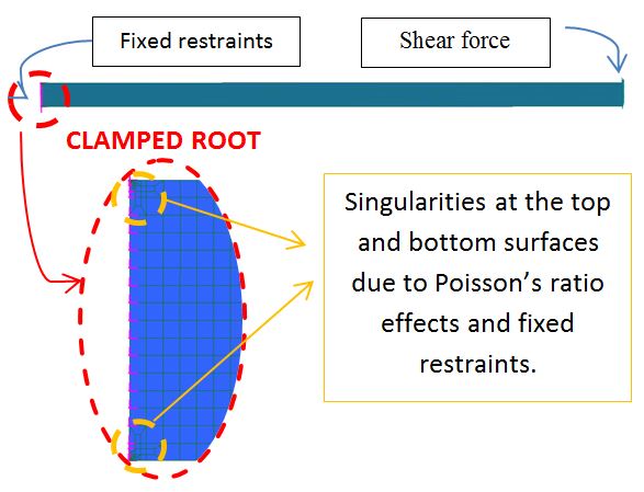
2D FEA model of a cantilever beam under a tip shear force – Singularities at the bottom and top surfaces of the root section.
The following are significant beam elasticity theory assumptions for this problem:
- Fiber stress at each section change linearly from the neutral axis to the top/bottom surfaces (σ = M y /I), where M is the bending moment, y is the vertical distance from the neutral axis and I is the relevant second moment of area.
- The normal stress at the top and bottom surfaces must be zero. These edges are free of applied forces.
In a 2D model, the clamped root is under horizontal tensile/compressive stresses. Due to Poisson’s ratio effect, the cross-section of the beam will tend to deform in the vertical direction. The top and bottom surfaces are free to do so, however note that we are imposing a fixity condition at the root in the Y direction. Suddenly, the top and bottom free surfaces are under the action of a singular point force respectively! The stress normal to the free surfaces jumps from zero stress to infinite stress.
This type of singularity occurs where mixed boundary conditions (displacement and stress boundaries) are applied to a node. On the one hand, the corner nodes must enforce a free edge condition (normal stress = 0). On the other hand, they must restrain the vertical movement of the clamped section. There is no way out but a singularity.
In the next lines, a mesh sensitivity study will be carried out. The objective of this study is to check if the stresses converge given a sufficiently small element size. A beam element model will be used as a benchmark. Thin beam elements will provide the classical Theory of Elasticity solution.
First of all we should check the displacements. As already mentioned, displacements should not be affected by stress singularities. We expect close agreement between the 2D model and the beam model in that regard (see next image).
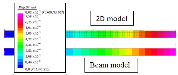
Tip displacements of a cantilever beam under tip shear load. 2D model vs Beam model.
The element size of the 2D model was then refined in a 2×2 fashion after each iteration. The tip vertical displacement and fibre stress at the root are extracted and compared to classical beam theory results. The following graph illustrates this process known as mesh sensitivity analysis.
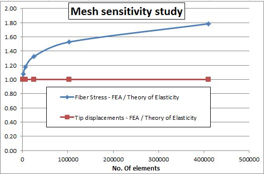
Mesh sensitivity study – Fiber stress at clamped section and tip displacements of 2D model against Theory of Elasticity predictions.
It is clear that the stresses at the corners do not converge even with more than 400.000 elements, which equates to less than 0.04% of the beam length!. In fact, this singularity is of a logarithmic type, and it is has been thoroughly studied in the literature (see [4] for further reference).
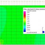
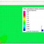
The up side is that St. Venant’s principle comes to the rescue. Stresses far from the singularity are correct. In the graph below, the fiber and normal stress at the top free surface has been contoured. The stresses vary with the distance from the tip. Normal stresses should be zero, because the edge is not normally loaded. The fiber stresses vary linearly as predicted by beam bending theory. Note however the singularity point at the root. Both fiber and normal stresses suddenly diverge.
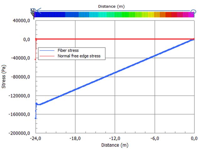
Fiber and normal stresses at the top surface varying from the tip to the clamped root section.
Note that if the solution were to be re-run with a Poisson’s ratio of zero, no singularity would occur!
Conclusions from this exercise:
- A mesh sensitivity study is a simple way to check potential singularity points in the mesh.
- Stress singularities do not affect displacement results, not even at the singularities.
- Stress singularities are likely to occur at supports when displacement boundary conditions and stress boundary conditions are mixed. The mesh convergence study shows a logarithmic divergence at the corner of the clamped cantilever beam section.
- The stress results elsewhere are not affected thanks to St. Venant’s principle.
- Beam elements are pretty much underrated compared to 2D and 3D elements. One single beam element was capable of predicting what 400.000 plate elements could not.
Further work:
- Introducing a elastic-plastic material will cut-off the singular stresses due to yield. For stress concentration locations, Neuber’s rule provides a method to calculate concentration factors past the elastic limit of the material.
References:
[1] Saint-Venant’s Principle, Wikipedia, available at: http://es.wikipedia.org/wiki/Principio_de_Saint-Venant (accessed 30 May 2015).
[2] Young, W., Budynas, R., (2001), Roark’s Formulas for Stress and Strain, Chapter 17 – Stress Concentrations, McGraw-Hill.
[3] Pilkey, D., Pilkey, W., (2008), Peterson’s Stress Concentration Factors, Wiley; 3 edition.
[4] Tullini, N., Savoia, M., (1995) Logarithmic stress singularities at clamped free corners of a cantilever orthotropic beam under flexure, University of Bologna.
This was a fantastic read, Thank you!
Very Useful Article , Thank you
Really useful.
What a exquisite writing!Love your work, thanks a lot, it really helped me out
Very nice
Excellent article!
Also, thank you very much for reaching out to me in such a timely manner.
When performing the last exercise (the one about mesh sensitivity),
the normal stresses at the top surface will never truly be zero, but some really close values to zero.
Acin has kindly explained that this is due to the fact that stress values are computed at Gaussian points, which are located inside the elements.
So, the values that are stored in the nodes on the top of the beam are extrapolated from these values. As you refine the mesh in the thickness direction, the Gaussian nodes will get closer to the top surface, but never quite on the top surface.
Therefore, while the result will approach 0, but never quite have that value.
Thank you for your help Acin!
Great!!!!!!!!!!!!!
Hello there! It’s hard to find anything interesting about this subject (that is not overly simplistic), because everything related to 3D seems rather complicated. You however seem like you know what you’re talking about 🙂 Thank you for finding time to write relevant content for us!
Thank you,
I realized that I don’t distinguish between stress concentration and stress singularities. Thank you for this clear and useful article.
Because I am dealing with concrete structure, I have always singularities in the connection between a plate ( 2D element) and a column ( 1D element). even when I do the nonlinear analysis I cant remove the singularity.
you mentioned that if the material nonlinearity is activated we can remove the singularity but it never happens with me, I cant overcome the singularity. do you have some advices maybe?
In such a case, I would not even bother with the singularity as stresses near the connection are not meaningful even if you were able to resolve the singularity. When I say not meaningful, I mean that this sort of modelisation (2D 1D element connection) is typically not sufficient to accurately resolve the stresses the real connection would undergo. This connection suffices and it is an efficient approach to calculate forces/reactions and displacements but when it comes to stresses at the connection a full 3D and more detailed modellisation of the connection should be done.
Hope that helps. Thanks for getting in touch.