Introduction
The Finite Element Analysis, also called the Finite Element Method (FEM), is a numerical technique to find numerical solutions to partial differential or integral equations of field problems. In stress analysis this field is the displacement field whereas in thermal analysis it is the temperature and in fluid flow it is the velocity potential function, and so on [1].
The FEM discretizes the physical domain into subdomains, the so-called finite elements, defined by a set of nodes; the arrangement of elements is called mesh. The unknown field is interpolated by shape functions, usually polynomial functions, depending on a set of discrete variables (i.e. field values at the nodes). By connecting elements the field becomes interpolated over the structure. The unknown field quantity is calculated via minimizing a function such as the potential energy in stress analysis; this procedure leads to a matrix of algebraic equations which are solved with a numerical scheme. As a result, the field values at the nodes are determined and extrapolated over the finite elements [1], [2].
In simple words, the FEM is a numerical method to solve partial differential equations by discretizing the domain into a finite mesh. Numerically speaking, a set of partial differential equations are converted into a set of algebraic equations to be solved for unknown at the nodes of the mesh. Bear in mind that FEA is an approximate solution of a mathematical representation of a physical problem. This is to say that, best case scenario FEA will replicate an analytical solution, whether the mathematical model is according to the real physical situation or not is another matter!
Versatility and applications
The power of FEA is its versatility. Over other numerical methods many advantages arise:
- applicable to many field problems: structural analysis, heat transfer, electrical/magnetical analysis, fluid and acoustic analysis, multi-physics, etc.
- no geometric restrictions,
- boundary and load conditions are easily applied as well as non-linear characteristics,
- many different materials, models and mathematical representations can be implemented, combined and coupled.
Although FEA has its inherent disadvantages, it has become widely used in structural analysis due to this set of unique features.
Solid mechanics
As I said, FEA is extensively applied to structural analysis, also called stress analysis, which is my major area of expertise and hence the focus of this blog. Typically, the input and output variables involved in linear static stress analysis are the following:
- Unknowns: displacements, strains, stresses.
A finite element solver always solves for displacements at the nodes. Once the displacements are known, other variables can be obtained. Strains are then derived via the compatibility equations from the displacement field, and stresses are subsequently derived from strains via the material constitutive matrix.
- Solid Mechanics equations:
- Equilibrium eqs.
 Typically in solid mechanics, any element under static equilibrium satisfies these set of equations.
 - Constitutive eqs. This is the relationship between strain
 and stresses. E.g. For an isotropic material, the Young´s modulus and Poisson’s ratio suffices to describe Hooke’s Law.
 - Compatibility eqs.
 These define how the strains are related to the displacements. Strains are just the derivatives of the displacements.
- Equilibrium eqs.
In total, we need to solve a problem consisting of 15 equations in which 9 are partial differential equations (good luck with that!). For simple cases, analytical solutions are available using the Elasticity theory, but for complex scenarios FEA is required [3].
- Input: Geometry, loading, restraints, material data.
The solid mechanics equations are fine…, but how does FEA solve for displacements?
Principle of Minimum Potential Energy (MPE)
The FEM uses a variational approach. Let’s consider an elastic body under the action of volume, surface and point loads. The MPE asserts that the structure shall deform to a position which minimizes the total potential energy of the system, this principle will allow us to calculate the displacements that satisfy this condition. The Potential energy (PE) of a structural system is defined as the sum of the strain energy (SE) and the work potential (WP)
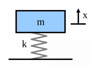
MPE applied to a spring-mass system:

Single degree of freedom mass-spring system
The SE of a mass(m) – spring(k) system is equal to
the WP of a force (f) acting in the X direction is
and therefore the PE is as follows:
If we apply the MPE principle, the PE minimized in the deformed configuration. In order to find this minimum let’s find the first derivative of the PE with respect to x and equate it to zero:
Which gives the position of equilibrium of the mass-spring system under the action of a single force – neglecting the work done by gravity:
MPE applied to a general elastic body:
The total potential energy of an elastic body under volume, surface and point forces can be expressed as shown below:
, where epsilon is strain vector and sigma is stress vector, D is the constitutive material matrix relating strain and stress.
, where u is the displacement vector, b is the volume force vector, t is the surface force vector and P is the nodal force vector. Hence, PE is as follows:
We can now apply the compatibility equations, those relating strains and displacements. mentioned before. In doing so, the strain vector can be regarded as a matrix derivative operator, denoted L, times the displacement vector, u. Finally, the PE is written as shown below:
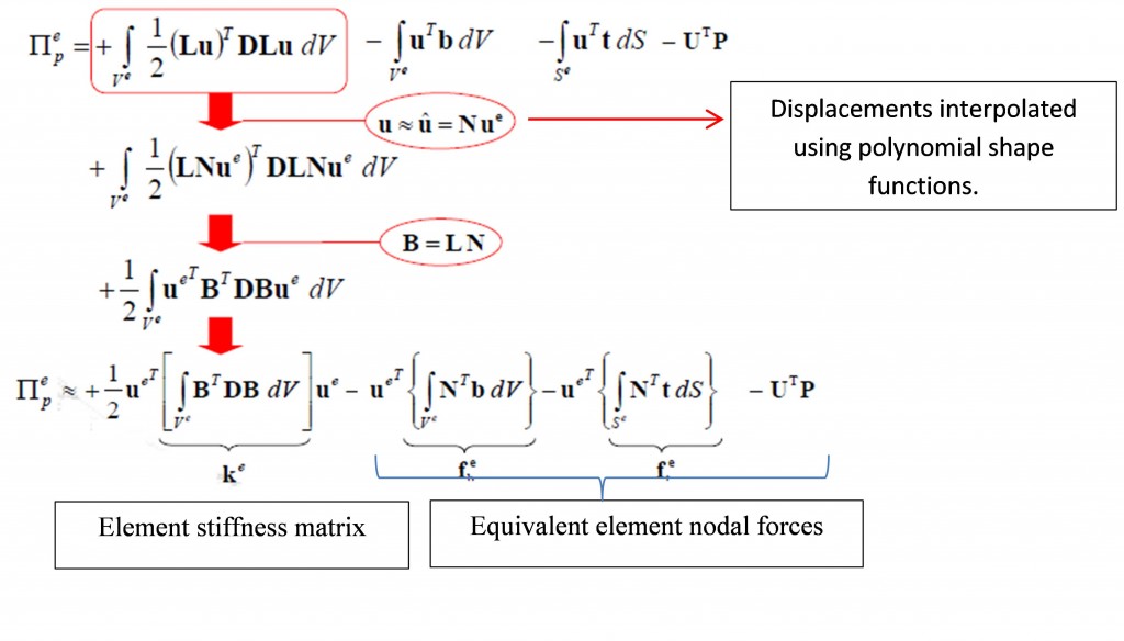
We got the total potential energy of a general elastic body!, but… where are the finite elements in all this? Nowhere to be seen, yet… When the FEM is applied to the MPE the volume and therefore the above equation is discretized into finite elements, within each element the unknown displacements are interpolated using polynomial functions. In doing so we are assuming that the displacements vary in a polynomial fashion within each element – which may not be correct – this is related to the so-called discretization error. Then, making use of the MPE we will be able to calculate the derivative of the PE with respect to the interpolated displacement field and get the desired solution to our problem.
Firsts things first. For each single element of the discretized finite mesh of our elastic body the MPE applies, and the previous equation ca be re-written as shown below. Note that the displacements have been interpolated using the shape functions and the super-index “e” denotes element variables of our discretized domain.

Derivation of the algebraic equations governing the deformation of an elastic body. The FEM is used to interpolate the displacement field and discretize the domain.
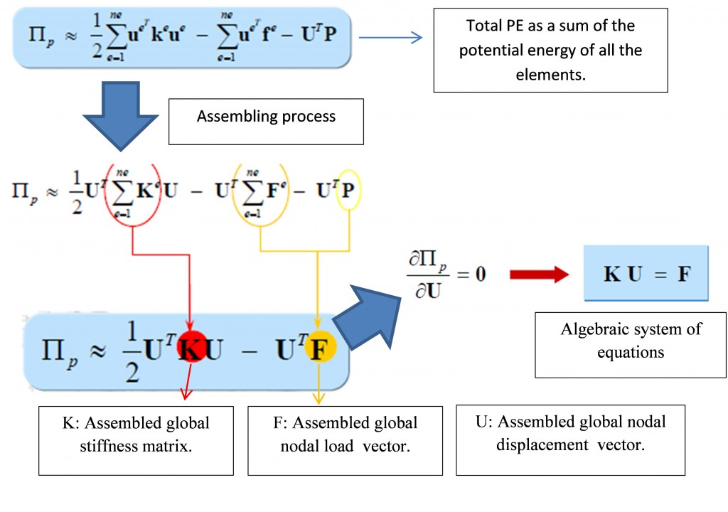
Now that the potential energy has been assessed on an element by element basis, the total potential energy of the system simply adds up to their sum. This is typically called the assembling process. The element stiffness matrix, element force and displacement vectors refer to the local element and have to be assembled into a global and much bigger matrix capturing the global stiffness matrix. For example, elements sharing nodes will contribute to the global stiffness matrix together. The stiffness terms coming from each different element is added together to get the total stiffness of the sharing node.

Global assembling process and application of the MPE principle using the FEM.
Similarly to the single mass-spring system where the MPE principle results in an algebraic equation, the variational approach produces a set of algebraic equations. The stiffness matrix K and the applied loads vector F will be used then to obtain the unknown nodal displacements.
The process is not yet finished, the restraints have to applied to the global stiffness matrix. As it is, this matrix is singular until the nodal restraints avoiding rigid body motions of the elastic body are set in place. In other words, no static equilibrium of the body can be found until the body is properly restraint. The restraint nodes, whose displacements is known are then removed from the global stiffness matrix. This final reduced stiffness matrix is, somehow, inverted and multiplied by the global force vector. And then, and not before, we will get the displacement vector under the deformed configuration :).
References:
Personally, I strongly recommend having a read through the following references which I find very useful to introduce yourself to FEA. Cook’s book very well deserves an honorable mention as it is regarded as the FEA bible. It is a must have on your shelf!
[1] Cook, R. D. (1995), Finite element modeling for stress analysis, 1st ed, John Wiley & sons, INC., University of Wisconsin – Madison.
[2] Fuenmayor, J., Ródenas, J.J., Tarancón, J.E., Tur, M. and Vercher, A., (2009), Cálculo estructural – Método de los elementos finitos, Departamento de Ingeniería Mecánica y de Materiales (DIMM), Universidad Politécnica de Valencia.
[3] Qi, H. (2006), What is Finite Element Analysis (FEA)?, University of Colorado, available at: http://www.colorado.edu/MCEN/MCEN4173/chap_01.pdf (accessed 20 May 2015).


Leave a Reply