1. Introduction: Need for meshless methods?
The typical Finite Element Method has been used with success in the industry as well as research for many years. However, there are certain situations where the mesh-based approach is not optimal. For example, simulations where the model undertakes large deformations are hard to deal with a mesh-based approach as the mesh becomes severely distorted leading to high inaccuracies and most likely termination of the simulation. One strategy to overcome this problem is remeshing, which means that the mesh is to be recreated during the simulation. However this approach is costly, often difficult to implement in 3D, and prone to errors as the simulation progresses.
Overcoming of the typical FE discretization disadvantages naturally led to the idea of mesh free methods where the domain is no longer to discretized using elements, but instead a set of data points – “nodes” – are used. Meshless methods are useful for a diversity of applications, but usually come with an increase in computational time required to run the simulations.
Liu [1] addressed the needs for mesh free methods, which include the handling of large deformations problems, the avoiding of stability issues, the representation of continuous variable fields and fluid representation and its interaction with structures. Some of these methods are the Element Free Galerkin (EFG), Finite Point Method, Point interpolation method, Boundary node method, SPH, etcetera. Due to the particle-like representation, these methods are usually Lagrangian as the material moves along with the nodes.
This article puts its focus on the SPH (Smoothed Particle Hydrodynamics) as it is one of the most famous meshless methods. The SPH method was originally developed in 1977 and has ben greatly developed ever since, and hence becoming one of the most used nowadays for a variety of purposes, including:
- Fluid simulations,
- Impact analysis,
- Fluid-Structure interaction,
- Metal forming, etc.
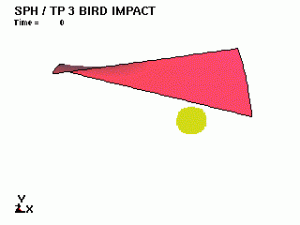
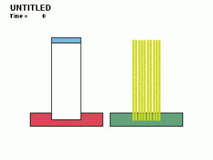
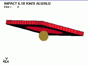
The following gallery showcases some examples coupling SPH to shell elements in LS-DYNA (click on the gallery to see the animated results). The examples and input decks are available in the following link: http://www.dynaexamples.com/sph and belong to LSTC.
- Impact of an idealized bird (SPH) against a turbine blade (lagrangian shells).
- Impact of two equivalent bars against a shell structure. The left bar is discretized using Lagrangian solid elements, the right one is discretized using SPH method.
- Impact of a ball against an aluminium sieve.
2. Smoothed Particle Hydrodynamics (SPH)
The Smoothed Particle Hydrodynamics (SPH) is a numerical scheme used for solving partial differential equations; originally developed for simulation of astrophysical problems [2; 3]. It was later modified and extended to solid and fluid dynamics problems [4]. It is a meshless Lagrangian method which makes use of interpolation to compute smooth field variables.
In the Finite Element Analysis the domain is discretized into elements whereas with SPH the domain is divided into particles, which are assigned mass, position and velocity, avoiding the classical problems associated with the mesh grid such as mesh distortion for large deflection problems. However, the use of this scheme also implies some disadvantages as zero energy modes, lack of consistency and tensor instability and the modelling of boundary conditions [5].
The aim of the following sections is to provide a basic understanding of the SPH methodology and cover the basic formulation and parameters required to run this numerical scheme.
2.1 Basic formulation
First of all, a different formulation had to be derived for the SPH, rather than the one used for typical FEA.
2.1.1 Kernel function
In order to interpolate field variables, instead of a grid and shape functions, a kernel interpolation is used. The value of a function f(x), at an x location, is represented by an integral form of the product of the function and a weighting factor known as the kernel function W(x-x^’,h) [6].
The brackets 〈 〉 symbolize a kernel approximation, h is the so-called smoothing length parameter which defines the domain of the kernel by determining the area of influence of the smoothing function, x’ is the new independent variable and Ω is the domain of the problem.
A better understanding may be acknowledged by looking at the following figure where the kernel function is used to approximate a field variable of a particle i within a radius κh, where κ is a constant applied to the smoothing length.
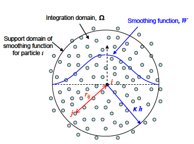
Domain and kernel function for a particle i [68].
The integral form of the gradient of the function can be calculated as the following expression:

Properties of the kernel function
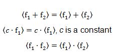
The kernel function satisfies some inherent properties and requirements [5]:
- Normalization condition:

- Compact support:
The kernel function is zero outside the kernel domainw which depends on the smoothing length κh. These properties ensure that the kernel function behaves as a Dirac delta function when the smoothing length tends to zero [1]:
- Dirac delta function behaviour:
 , and therefore,

- Kernel approximation properties:
Examples of Kernel functions
Various options exist to define the kernel function; the most famous ones are the Gaussian and the polynomial splines.
- Gaussian function
![]()
Where the parameter r=(x-x^’)/h is a parameter which makes de domain of the function non-dimensional and d is the number of dimension of the problem (1D, 2D, 3D). This kernel and its derivatives are smooth and stable even for a distorted particle distribution [7].
- Cubic B-spline
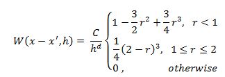 Where C is a scaling factor which assures the compliance with the kernel function properties and depends on the dimension of the problem (e.g. d=1 for 1D):
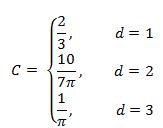
This spline is used for its narrower support. The B-spline is zero for ranges beyond the kernel domain whereas the Gaussian kernel tends to zero but it is not exactly equal to zero, increasing with the radius of support. However, due to the piecewise definition of the B-spline is less smooth and stable [7].
According to the LS-DYNA theory manual [8] the kernel function implemented in their code is the B-spline. A comparison between these two kernel functions is presented in the following figure.
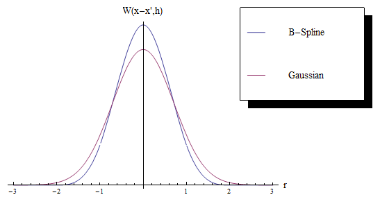
Kernel functions scaled over the non-dimensional domain r.
Discretization
The integral form of the interpolation can be discretized as the summation of N discrete points:

The value of the filed function for a particle i is the addition of the contribution of its neighbouring particles j within the interpolation range κh, commonly 2h. The term m_j/ρ_j is the volume associated to each particle j. It is important to notice that contrary to the shape functions in FE the value of the function at a node/particle i is not its nodal value, it is the contribution of a sum of particles within its neighbouring domain.
The gradient of the function may be written as:
 where
where
![]() and r_ij is the distance between i-j particles.
and r_ij is the distance between i-j particles.
2.2 Implementation of conservation equations
Once the basic formulation has been covered it can be applied to obtain the conservation equations which govern the particle motion and its thermodynamic state.
A detailed calculation of the derivation process was carried out by Prof. Vignjevic [5] through the use of the kernel previously properties and other mathematical theorems. The final discretized conservation equations are shown below.
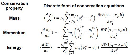
Where σ_j^αβ are the components α and β of the stress at a particle j. It is also worth to mention that acceleration vectors, such as gravity, may be summed to the total momentum. Artificial viscosity is also commonly used to improve the numerical stability of the scheme.
Note that the momentum equation may be written in different forms depending on the approximation of choice. E.g In LS-DYNA [8] the following approximations are available: default formulation (0), renormalization approximation (1), symmetric formulation (2), symmetric renormalized approximation (3), tensor formulation (4), fluid particle approximation (5), or fluid particle with renormalization approximation (6). The renormalized approximation refers to a normalized kernel used in order to achieve 1st order consistency. The fluid approximation notorably used to represent fluid behaviour is shown as follows.
 2.3 Equation of state
A thermodynamic relation between the state variables is needed in addition to the previous set of conservation equations. The EoS can be regarded as a constitutive equation linking the state variables such as temperature, pressure, volume or internal energy in a homogeneous material. It is used to describe the behaviour of fluids, solids and gases. Common relationships between pressure and two other state variables are defined in thermodynamics as:
![]() Where the state variables and parameters are defined as:
Where the state variables and parameters are defined as:
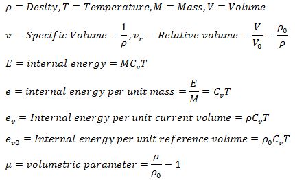
Some useful EoS introduced in LS-DYNA [8] and other FE packages are:
- Linear polynomial EoS
 Where C_i are user defined constants depending on the material.
- Gruneisen EoS
 Where, the new parameters are defined as follows. C is the speed of sound in the material, S_1,S_2 and S_3 are coefficients of the slope u_s – u_p, γ_0 is a Gruneisen parameter and a is the first order volume correction to γ_0.
- Murnaghan EoS
In its original form, it comes from relating a linear behaviour of the bulk modulus of a solid compressed to a finite strain with respect to the pressure:

Where K_0 is the bulk modulus and K_0′ is its first derivative with respect to the pressure.
- Tabulated EoS

Where e_V is the natural logarithm of the relative volume, C (Pa) is a constant and γ is the adiabatic index. Introducing up to 10 points, the pressure can be then tabulated and extrapolated if needed.
2.4 Variable smoothing length
The smoothing length defines the interaction range between particles. If the smoothing length is set to remain constant the separation between them may become so large that the particles will no longer interact with each other; on the other side, the separation may be too small signficantly slowing down the simulation. In order to avoid this problem a variable smoothing length can be implemented in LS-DYNA [9]:

Where d is the dimension of the problem and div(v) is the divergence of the flow. Additionally, the smoothing length can be limited to vary within specific ranges depending on the initial smoothing length calculated at the beginning of the simulation [9]:
![]()
Where HMIN and HMAX are constants applied to the initial smoothing length (h_0) and CLSH is a constant. All these constants can typically be modified.
2.5 Sort of neighbours
The neighbour search is one of the main tasks for every SPH time step. It may be a very CPU consuming task depending on the algorithm type selected [5]. Basically two options can be chosen in LS-DYNA:
- Global computation: every particle is mutually checked with the rest globally. This can lead to a very time-consuming algorithm and it is not recommended for large problems.
- Bucket sort: A grid of size κh is generated and each particle is assigned to one of the boxes, then the searching for each particle starts checking other particles within its own and neighbouring boxes as illustrated below.
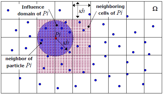
Bucket sort based algorithm [7].
2.6 Boundary conditions
Boundary conditions need a special treatment in the SPH method. According to Campbell et al. [10] SPH approximations are not strict interpolants. Hence, the variables in the particle location are not equal to the particle variables and trying to impose a free edge boundary condition to the particles next to the outer surface of a component will lead to the non-satisfaction of the boundary condition (the inner particles will interact with the ones located at the edge). Several approaches have been developed and are summarized below [7]:
- Boundary force method: fixed particles are distributed along the boundaries introducing a force to the inner particles as a function of the distance to the boundary [57].
- Ghost particles – Symmetry planes: a symmetry plane is created and the real particles are mirrored into ghost particles which have the same mass, pressure and velocity as the real ones. This effectively creates a symmetry condition.
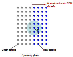
Symmetry plane boundary condition in SPH modelling [68].
- Semi-analytical approaches: there are many semi-analytical approaches covered in the literature. For example Prof. Manenti [7] describes the following where the boundary conditions are approximated through analytical integration terms. Solid boundaries are placed as fluid but unlike the ghost particle method these are an infinite number, producing a continuous boundary.
2.7 Contact and FE coupling
Contact handling in SPH has been ignored and dealt over the years through the conservation equations implied by the SPH formulation. However, this leads to some penetration when SPH particles from different components interact [10]. A literature survey about this topic reveals some unique SPH contact handling algorithm such as [10] and [11]. The particle to particle contact is commonly used instead of the particle to surface contact due to the difficulties defining a 3D surface out of SPH particles.
Nevertheless, nodes-to-surface contacts have been widely used for SPH – FE coupling. The set of SPH nodes is defined as a slave while the FE master surface is defined as a master. A slave node is simply a nodal point, a SPH particle, whereas a surface is defined using the side of a finite element on the FE component global surface [12].
The most common approach to model contact is the penalty-based method, when a penetration occurs, node-to-node or node-to-surface, a force proportional to the penetration depth is applied to resist and eliminate penetration.
Example: LS-DYNA solves the SPH-FE coupling with a nodes-to-surface penalty based contact, where each SPH slave node is checked for penetration against the master FE surface.
2.8 Time step
There are many forms of SPH time stepping schemes, all of them explicit schemes such as leap-frog, predictor-corrector method and the low order Runge-Kutta. They have been employed efficiently throughout the years [6].
According to the LS-DYNA theory manual [8], a first order scheme is implemented. The time step varies according to the following formula:
![]() Where C_CFL is a constant and h_i, c_i, v_i are the smoothing length, the adiabatic speed of sound and velocity for a particle i.
Where C_CFL is a constant and h_i, c_i, v_i are the smoothing length, the adiabatic speed of sound and velocity for a particle i.
Note that when SPH and FE elements coexist for fluid-structure interaction problems, the time-step can be governed by the SPH rather than the FE. This is for example the case when rigid elements are used to describe the structure.
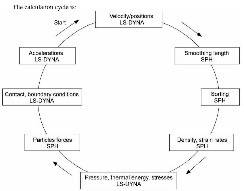
SPH calculation cycle for each time step in LS-DYNA software [8].
2.9 Limitations and shortcomings
The SPH method have its inherent limitations. A list and brief description of each one is covered below. Prof.Vignjevic [5] described them as follows:
2.9.1 Consistency issues
The SPH continuous formulation shows to be inconsistent in its domain, 2h, due to the incompleteness of its kernel support. While in its discrete form, if the particles have an irregular distribution, it loses its 0th order consistency.
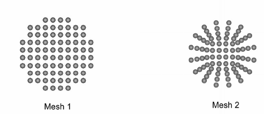
Different SPH distribution types as illustrated in the LS-DYNA manual [8].
The grid must be as regular as possible and without large variations in order to avoid 0th order inconsistency, Mesh 1 above would be preferable to a non-uniform Mesh 2. 1st order consistency may be achieved by a kernel normalisation (CNSPH) leading to a different kernel and conservation equations approximation previously mentioned.
2.9.2 Tensile instability
Swegle et al. [13] provided a stability criterion for SPH equations, unstable growth occurs when this condition is reached:![]() Where W^” (x-x’,h) is the second kernel derivative and σ is the stress (σ>0 means tension and σ<0 means compression). This instability arises due to numerical issues from the interaction of the kernel interpolation and constitutive equations changing the nature of the partial differential equations. This results in a clustering of SPH particles which often manifests itself as a tensile mode but it is not restricted to it [5].
Where W^” (x-x’,h) is the second kernel derivative and σ is the stress (σ>0 means tension and σ<0 means compression). This instability arises due to numerical issues from the interaction of the kernel interpolation and constitutive equations changing the nature of the partial differential equations. This results in a clustering of SPH particles which often manifests itself as a tensile mode but it is not restricted to it [5].
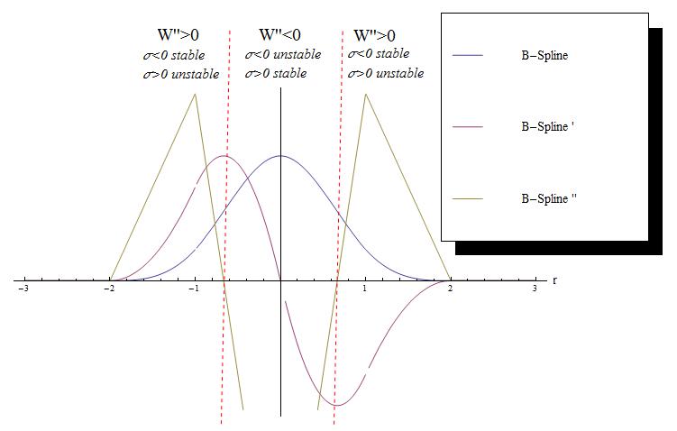
Swegle et al. stability regions for the cubic B-spline kernel.
2.9.3 Zero energy modes
Spurious modes, known as zero energy modes, are often found in the FEM and it is not a self-unique feature. They are also present in particle methods such as SPH. There are certain situations when non-physical nodal displacement patterns produce zero strain energy. The main cause being that the field variables and their derivatives are calculated at the particle locations, which for certain field combinations may lead to zero field gradients when interpolated, making these modes easily excitable. Some solutions and further explanation and literature are covered by Prof. Vignjevic [5].
3. Conclusions
- Mesh-free methods were developed due to inherent problems of the mesh-based approach discretization. SPH can be used to model large deformations avoiding instabilities and extending the simulation time. On the other hand, SPH has limitations of its own such as significant simulation storage and elapsed time consumption. SPH also presents some formulation shortcomings.
- SPH adds a whole new set of variables to the simulation. And hence, a proper understanding of these variables is needed to be reckoned by the analyst.
- Some of the main SPH findings are:
- Field functions are interpolated among the domain where the smoothing length plays a critical role.
- There are different formulations according to the implementation of the momentum equation.
- Boundary conditions are treated differently rather than the usual FE boundary conditions.
- Contact algorithms between FE-SPH are a key feature for fluid-structure interaction and may be modelled in different ways. A surface-to-nodes contact algorithm is widely used in this regard.
References:
[1] Liu, G. R. (2003), Mesh free methods: moving beyond the finite element method, 1st ed, CRC Press LLC, Washington D.C.
[2] Lucy, L. B. (1977), “A numerical approach to the testing of the fission hypothesis”, The astronomical journal, vol. 82, no. 12, pp. 1013-1024.
[3] Monaghan, J. J. (1982), “Why particle methods work”, SIAM J. SCI. STAT. COMPUT., vol. 3, no. 4, pp. 422-433.
[4] Monaghan, J. J. (1992), “Smoothed Particle Hydrodynamics”, Annual Review of Astronomy and Astrophysics, vol. 30, pp. 543-574.
[5] Vignjevic, R., ( 2010), Review of Development of the Smooth Particle Hydrodynamics (SPH) Method, School of Engineering, Cranfield University.
[6] Monaghan, J. J. (1988), “An introduction to SPH”, Computer Physics Communications, vol. 48, no. 1, pp. 89-96.
[7] Manenti, S., ( 2009), A Smoothed Particle Hydrodynamics: Basics and Applications, Lecture notes ed., Dipartimento di Meccanica Strutturale, Università degli Studi di Pavia.
[8] Livermore Software Technology Corporation (LSTC) (2006), LS-DYNA Theory manual, Livermore, California.
[9] Livermore Software Technology Corporation (LSTC) (2007), LS-DYNA Keyword user’s manual (v. 971), Livermore, California.
[10] Campbell, J., Vignjevic, R. and Libersky, L. (2000), “A contact algorithm for smoothed particle hydrodynamics”, Computer Methods in Applied Mechanics and Engineering, vol. 184, no. 1, pp. 49-65.
[11] Monaghan, J. J. (1989), “On the problem of penetration in particle methods”, Journal of Computational Physics, vol. 82, no. 1, pp. 1-15.
[12] Attaway, S. W., Heinstein, M. W. and Swegle, J. W. (1994), “Coupling of smooth particle hydrodynamics with the finite element method”, Nuclear Engineering and Design, vol. 150, no. 2–3, pp. 199-205.
[13] Swegle, J. W., Hicks, D. L. and Attaway, S. W. (1995), “Smoothed Particle Hydrodynamics Stability Analysis”, Journal of Computational Physics, vol. 116, no. 1, pp. 123-134.
It was interesting when you said that the mesh needs to be recreated during the simulation process in order to ensure that the mesh won’t become too distorted during the simulation process. This reminded me of industries that need industries that use cloud computing to ensure that they have access to the use of mesh-free particle-based simulation software. I could imagine how this type of software could allow a company to manage projects well as they could trace the simulation progress all in one view.